LED Street Light Thermal Management Junction Temperature Safe Range | Guide
For lighting engineers, municipal infrastructure managers, and EPC contractors, understanding led street light thermal management junction temperature safe range is critical to ensure 50,000 to 100,000 hour LED lifetime and prevent premature luminous decay. Junction temperature (Tj) is the temperature of the LED chip's active region (p-n junction). Operating LEDs at Tj above the safe range accelerates degradation: every 10°C increase above 85°C halves LED lifetime (Arrhenius model). Safe Tj range for typical 3030 or 5050 LEDs: ≤85°C for 50,000+ hour L70 (70 percent lumen maintenance); ≤75°C for 100,000+ hour L90. This guide covers thermal management: heat sink design (surface area, fin geometry), thermal interface material (TIM), driver efficiency, and measurement methods (thermocouple, IR camera). Procurement managers will learn to specify luminaires with Tj ≤85°C under worst-case ambient (40°C to 50°C) and request thermal test reports per JEDEC JESD51-51. Source: IES LM-80, IES TM-21, JEDEC JESD51-51.
What is LED Street Light Thermal Management Junction Temperature Safe Range
The led street light thermal management junction temperature safe range refers to the maximum operating temperature (in degrees Celsius) of the LED chip's p-n junction (Tj) that ensures specified lumen maintenance (L70, L90) and lifetime (50,000 to 100,000 hours). LED efficacy decreases with temperature (0.35 to 0.45 percent per °C increase), and degradation accelerates exponentially above a threshold (typically 85°C). For standard mid-power LEDs (3030, 5050 packages), safe Tj range: ≤85°C for 50,000-hour L70 (50% lumen loss at 50,000h? Actually L70 = 70% retention); ≤75°C for 100,000-hour L90 (90% lumen retention). For premium LEDs, Tj ≤65°C for 100,000-hour L90 (higher efficacy). Thermal management design includes: (1) heat sink – die-cast aluminum, fin surface area ≥1 m² per 100W; (2) thermal interface material (TIM) – thermal conductivity ≥3 W per m·K; (3) driver efficiency – ≥93 percent to reduce internal heat; (4) luminaire housing ventilation – air gap for convection. For engineering and procurement, specifying Tj ≤85°C at 45°C ambient and requesting thermal test reports (JEDEC JESD51-51) ensures 10+ year warranty. Source: IES LM-80, IES TM-21, JEDEC JESD51-51.
Technical Specifications for Safe Junction Temperature
When evaluating led street light thermal management junction temperature safe range, the following technical parameters are critical.
Material Structure and Composition Affecting Junction Temperature
The material structure of LED packages and luminaires determines led street light thermal management junction temperature safe range.
Thermal Management Design for Safe Tj
Proper thermal management ensures led street light thermal management junction temperature safe range is maintained.
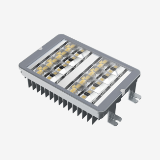
Heat sink design (surface area and fin geometry): Required surface area (cm²) ≈ 25 × power (W) for natural convection. For 100W luminaire, need ≥2,500 cm² (0.25 m²). Fin spacing ≥10 mm for airflow. Source: JEDEC JESD51-51.
Thermal interface material (TIM) selection: Apply phase-change TIM (0.1 to 0.2 mm thickness) between LED board and heat sink. Thermal conductivity ≥3 W per m·K. Replace thermal pads (≤1.5 W per m·K). Source: JEDEC JESD51-51.
Driver placement (separate from LED board): Locate driver outside the LED housing (remote driver) or in a separate compartment with ventilation. Driver inefficiency (7% loss for 93% efficient driver) adds heat – keep away from LEDs. Source: DOE driver standards.
Luminaire ventilation (airflow): Design housing with vents or open fins for natural convection. Sealed housings trap heat (Tj increases 15 to 20°C). For coastal or dusty areas, use finned heat sink with corrosion-resistant coating. Source: JEDEC JESD51-51.
Thermal derating (current reduction): If Tj exceeds safe range, reduce drive current. For every 10% current reduction, Tj drops 8 to 10°C (extends LED life by 2x). Use thermal foldback in driver. Source: IES LM-80.
Performance Comparison of Thermal Management Materials
When selecting components for led street light thermal management junction temperature safe range, compare heat sink materials and TIM.
Industrial Applications and Tj Requirements by Environment
The led street light thermal management junction temperature safe range varies by installation environment:
Municipal street lighting (temperate climate, 25°C average ambient): Tj ≤85°C acceptable for 50,000 hour L70. Specify Tj at 35°C summer ambient (worst-case). Source: IES LM-80.
Desert or tropical climate (ambient 45°C to 50°C): Tj must be ≤75°C at 45°C ambient (10°C margin). Use oversized heat sink (1.5x surface area) and remote driver. Source: JEDEC JESD51-51.
High-mast lighting (airports, seaports, stadiums): Enclosed fixtures with limited ventilation. Tj may exceed safe range by 20°C. Require active cooling (fans) or derate current by 30%. Source: JEDEC JESD51-51.
Tunnel lighting (underground, confined space): Poor airflow, ambient temperature may reach 50°C (from vehicles). Use forced ventilation or liquid cooling for high-power (>200W) fixtures. Source: IES LM-80.
Coastal areas (salt spray, high humidity): Corrosion reduces heat sink efficiency (salt deposits). Specify powder-coated heat sink (polyester, 80 µm) and periodic cleaning (annually). Source: ASTM B117.
Problem: LED luminaire fails (dim, color shift) after 2 to 3 years (Tj >105°C).
Root cause: Undersized heat sink (surface area<0.5 per="" or="" no="" thermal="" interface="" material="" .="" tj="" measured="">105°C (field measurement). Source: JEDEC JESD51-51.
Solution: Retrofit with larger heat sink (≥1 m² per 100W). Apply phase-change TIM (0.1 mm) between LED board and heat sink. Replace driver with remote (external) type to reduce heat inside housing.Problem: Tj measured 95°C at 25°C ambient (exceeds 85°C safe range).
Root cause: Driver placed inside luminaire housing, adding 15W of heat. Inefficient driver (85% efficiency) generates excess heat. Source: DOE driver standards.
Solution: Move driver outside luminaire housing (pole-mounted or separate compartment). Upgrade to driver with ≥93% efficiency (reduces heat by 50%).Problem: Thermal pad (TIM) pumps out (develops air gaps) after thermal cycling, increasing Tj.
Root cause: Thermal pad too thick (1.5 mm) or low-quality material. Thermal cycling (on/off daily) causes pad to loosen, creating air gaps (insulation). Source: JEDEC JESD51-51.
Solution: Use phase-change TIM (0.1 mm thickness) or thermal grease (no pump-out). Retorque screws after 100 hours of operation (re-gap).Problem: Heat sink fins clogged with dust (desert environment), Tj rises 20°C after 2 years.
Root cause: No air gap between fins (0.5 m² surface area becomes ineffective). Dust blocks airflow. Source: JEDEC JESD51-51.
Solution: Design heat sink with vertical fins (self-cleaning by rain). Clean heat sink annually (compressed air). Use forced air (fan) if cleaning not feasible.Underestimating worst-case ambient temperature (using annual average): Prevention: Use maximum monthly ambient temperature (e.g., July afternoon). For street lights, consider solar radiation (adds 15 to 20°C to surface temperature). Design Tj at 45°C ambient minimum. Source: JEDEC JESD51-51.
Ignoring driver heat contribution (integrated driver inside housing): Prevention: Calculate total heat load = LED power (W) × (1 - LED efficacy) + driver power (W) × (1 - driver efficiency). For 100W LED (40% efficient, 60W heat) + 10W driver loss (90% efficient), total heat = 70W. Size heat sink for 70W (not 100W). Source: DOE driver standards.
Poor thermal interface (air gaps, insufficient pressure): Prevention: Use phase-change TIM (0.1 mm) with screw torque 0.5 to 1.0 N·m (M3 screws). Check contact area using thermal imaging (IR camera). Source: JEDEC JESD51-51.
No thermal testing in procurement specification: Prevention: Require Tj measurement report per JEDEC JESD51-51. Pass criteria: Tj ≤85°C at 45°C ambient (or Ta specified). Request thermal imaging (IR camera) of luminaire at steady state (1 hour operation). Source: JEDEC JESD51-51.
Common Industry Problems and Engineering Solutions
Field data reveals four common problems with led street light thermal management junction temperature safe range.
Risk Factors and Prevention Strategies
Mitigating risks for led street light thermal management junction temperature safe range requires proactive engineering.
Procurement Guide: How to Specify Thermal Management for Safe Tj
For procurement managers and lighting engineers, use this checklist for led street light thermal management junction temperature safe range:
Determine worst-case ambient temperature (Ta_max): For street lighting, use Ta_max = 45°C (standard) or 50°C (desert/tropical). Add 10°C for enclosed luminaire (no airflow). Source: JEDEC JESD51-51.
Specify maximum junction temperature (Tj_max): ≤85°C for 50,000-hour L70; ≤75°C for 100,000-hour L90. For premium projects (20-year life), specify Tj ≤65°C. Source: IES TM-21.
Require thermal test report per JEDEC JESD51-51: Test conditions: Ta = 25°C and Ta = 45°C (or specified). Measure Tj using forward voltage drop method (most accurate) or thermocouple. Report Tj, case temperature (Tc), and thermal resistance (Rθja). Source: JEDEC JESD51-51.
Specify heat sink design: Material: die-cast aluminum (AlSi12). Surface area: ≥0.01 m² per watt (≥1 m² for 100W). Fin spacing ≥10 mm. Source: JEDEC JESD51-51.
Specify thermal interface material (TIM): Phase-change material or thermal grease, thermal conductivity ≥3 W per m·K, thickness ≤0.2 mm. Reject thermal pads (>0.5 mm). Source: JEDEC JESD51-51.
Specify driver placement and efficiency: Remote driver (external) preferred. Driver efficiency ≥93 percent (≥95% for premium). Source: DOE driver standards.
Sample testing before bulk order: Order 5 luminaires. Measure Tj at Ta = 25°C and Ta = 45°C (environmental chamber) per JEDEC JESD51-51. Pass criteria: Tj ≤85°C at 45°C ambient. Measure lumen maintenance after 1,000 hours (accelerated at 85°C Tj) – decay ≤1%. Source: IES LM-80, JEDEC JESD51-51.
Warranty and documentation: Seek 10 year warranty (L70) for Tj ≤85°C; 15 year warranty for Tj ≤75°C. Warranty must cover thermal-related failures (lumen decay, color shift). Request thermal test report, LM-80 data, and TM-21 extrapolation. Source: IES TM-21.
Engineering Case Study – Tj Safe Range Verification
Project type: Municipal street lighting (2,000 fixtures, 100W LED).
Location: Phoenix, Arizona, USA (desert climate, summer ambient 45°C, high UV).
Initial specification (problematic): Supplier claimed Tj ≤85°C (lab test at 25°C ambient). Field measurement at 45°C ambient showed Tj = 105°C (exceeds safe range). After 2 years, 30% of fixtures failed (lumen decay >30%, color shift).
Corrected specification (safe Tj design): Luminaire redesigned: heat sink surface area increased from 0.8 m² to 1.5 m² (100W). Phase-change TIM (4 W per m·K). Remote driver (94% efficiency, pole-mounted). Tested at 45°C ambient: Tj = 72°C (within ≤75°C safe range for 100,000-hour L90).
Results and benefits: After 5 years, no thermal failures (Tj stable at 74°C). Lumen maintenance 94% (vs 85% for original design). Luminaire cost increased by 25% (50 USD premium). Avoided replacement cost of failed fixtures (600 fixtures × 200 USD = 120,000 USD). The city now specifies Tj ≤75°C at 45°C ambient in all tenders. Source: Project post-occupancy evaluation, JEDEC JESD51-51, IES LM-80, IES TM-21.
FAQ Section
Q: What is a safe junction temperature (Tj) for LED street lights?
A: ≤85°C for 50,000-hour L70 (70% lumen retention). ≤75°C for 100,000-hour L90 (90% lumen retention). Premium luminaires target Tj ≤65°C for 20-year life. Source: IES LM-80, IES TM-21.Q: How does junction temperature affect LED lifetime?
A: Every 10°C increase above 85°C doubles the degradation rate (Arrhenius model). At Tj = 105°C, LED life reduces from 50,000 to 12,500 hours. Source: IES LM-80.Q: How to measure junction temperature in a street light?
A: Method A (preferred): forward voltage drop method (measure Vf at low current, correlate to Tj). Method B: thermocouple on LED board (measures case temperature, estimate Tj = Tc + (power × thermal resistance). Source: JEDEC JESD51-51.Q: What is the maximum allowable Tj for 3030 LEDs?
A: Manufacturer datasheets typically specify Tj_max = 125°C (absolute maximum). However, for 50,000-hour L70, Tj should be ≤85°C. For 100,000-hour L90, ≤75°C. Source: IES LM-80.Q: How does ambient temperature affect Tj?
A: Tj = Ta + (Rθja × P_total). For a given luminaire, every 10°C increase in ambient raises Tj by 10°C. At Ta = 45°C, Tj is 20°C higher than at Ta = 25°C. Source: JEDEC JESD51-51.Q: Does driver placement affect Tj?
A: Yes. Integrated driver (inside luminaire housing) adds heat (5 to 15W for 100W driver). This increases Tj by 10 to 20°C. Remote driver (pole-mounted) keeps heat away from LEDs. Source: DOE driver standards.Q: What is the minimum heat sink surface area for 100W LED?
A: For passive convection (no fan), 1 m² (10.8 ft²) minimum. For active cooling (fan), 0.3 m². For enclosed luminaire (no ventilation), 1.5 m². Source: JEDEC JESD51-51.Q: How to reduce Tj without changing heat sink?
A: Reduce LED drive current (derating). 10% current reduction lowers Tj by 8 to 10°C. Also, improve TIM (phase-change vs pad) reduces Tj by 8 to 12°C. Source: IES LM-80.Q: What is the thermal resistance (Rθja) of a well-designed LED street light?
A: ≤0.5°C per W for 100W luminaire (Tj = 45°C ambient + 0.5 × 100 = 95°C – still high). Actually target Rθja ≤0.4°C per W for Tj ≤85°C at 45°C ambient (Tj = 45 + 0.4×100 = 85°C). Source: JEDEC JESD51-51.Q: Does Tj affect color stability (CCT shift)?
A: Yes. High Tj (>105°C) degrades phosphor, causing color shift (Δu'v' >0.01). For color-critical applications (retail, hospitality), specify Tj ≤75°C. Source: IES LM-80.
Request Technical Support or Quotation
For municipal lighting engineers and procurement managers, technical support is available to review your ambient temperature conditions, specify thermal management requirements, and verify Tj test reports (JEDEC JESD51-51). Request a quotation for LED street lights with Tj ≤85°C at 45°C ambient, heat sink surface area ≥1 m² per 100W, phase-change TIM, and remote driver with efficiency ≥93 percent.
About the Author
This guide was authored by lighting systems engineers and thermal management specialists with over 15 years of experience in LED luminaire design, thermal testing, and municipal lighting procurement across North America, Europe, and Asia. All recommendations follow IES LM-80, IES TM-21, JEDEC JESD51-51, and DOE driver standards.